DISCLAIMER: I started documenting a lot of details of my code but after a while realised this was costing more time and effort than it's worth. The goal is also not to explain how the code of my drum machine works, but how we go from an idea to a machine.
I will track my progress chronologically and write the dates for each post as well as the github commit hash or pull request. Seeing as I already made some progress before I decided to write it down, the first post is quite large.
Github commit: 1213b54
My c++ knowledge starting out is quite limited. I did some arduino and used c++ to solve a couple of Advent of Code questions, but that's it. I do have coding experience though, so that helps a lot. For the c++ thought, I started reading "The Audio Programming Book". This is a great start for some basics in audio programming in c/c++. Another great resource is the public available code by Emilie Gillet for her Mutable Instruments modules, found here: https://github.com/pichenettes/eurorack/. I have the Mutable instruments peaks module, of which the drum setting plays a drum sound based on an input trigger. Seeing as a sequencer is basically just triggering sounds at predefined times, this mutable Peaks code should of use. In the style of learning by doing, I did not stop to first read these sources though, just got stuck in as quickly as possible.
My high level plan is for writing the code is the following:
1. Create developing environment for my project
2. Create a simple outline for the program
3. Code a simple sinewave
4. Add an attack-decay envelope to the sinewave
5. Trigger this sinewave at predefined times
6. Shape the soundwave to a parametrized kickdrum
7. Add parametrized hihat sound using kickdrum as template
8. Add parametrized snare-drum sound using kickdrum as template
9. Write the sequencer logic
10. Write algos (Pretty empty statement this one here, but will think about algorithms after the sound generation part is in place).
Note that I don't include any bootstrapping of the microcontroller yet. The end product here is a program that writes an audio file to my hard drive. Taking it to a chip is a problem for future Morten.
Development Environment
Just a quick tip for mac users who want linux without dual boot and such, I used orbstack for the first time to deploy a containerised archlinux distro and it works like a charm.
During development I want to output both audio as well as a plot of the audio each time I compile and run. The plot is very useful in identifying any issues with the waveform. I saw that c++ programs, generally use a makefile to define how/what to compile, so I made a simple one for this project. Since the program outputs raw audio, I use the sox command line tool to convert this to a .wav file. Also I don't plot the graph within the c++ program, but just a simple text file with x,y coordinates. This is turned into a graph using plotutils. All these steps I combined in a simple bash script, so for every time I want to run, I just execute run.sh
Program outline
I thought I'd start out with what seems most straightforward to me. I'm picturing a sequencer as a simple loop of say 16 events, where an event can be either 'do nothing' or 'trigger 1, 2 or 3 sounds' (since I am limiting myself to 3 sounds atm). These events are triggered at set times based on the BPM (for now I won't care about bpm tho). And these times could easily be calculated in time (e.g. seconds). Since however our program doesn't deal with seconds as such (yet), but with positions (where time in seconds = position / sample rate), I try to think in terms of position. So my sequencer for the time being will be simple: when the program starts, the position will start increasing and at predefined positions the sound will be triggered. With this approach I don't have to think about real world time yet as part of the program logic. This only comes into play when I export the raw audio.
For the sound generation, I create a class for each type of sound. This project is a perfect example of where object oriented programming is the bees knees. It provides the flexibility to easily adjust parameters between hits or have simultaneous hits of the same instrument just by initialing a new class instance. My implementation will be that when the position is reached for e.g. a kick drum hit, then we set all the parameters for that hit (decay, overdrive etc.) and start the hit. The processing of the hit is defined by the process function in the class and the output returned to the main loop. Thinking ahead I can later easily replace the manually inputted trigger position by a sequence algorithm of my choosing. Hope that makes sense...
Lastly I am writing the program to later work with a 16bit DAC and thus my output is 16bit. Before I started I had no idea what that meant, but it simply means my output ranges from −32,768 to 32,767. So where a simple sine wave as y(t)=sin(phi*t) ranges from -1 to 1, we'd have to scale this to the 16 bit range by multiplying it by 32,767. This will output a wave that looks like this (sort of):
The kick drum
First sound I wrote an algorithm for is the kick. I remember the kick from the Ableton DS Kick (midi instrument) was quite nice, so checked that out as inspiration. It has a couple of parameters to tweak, and by comparing the tweaked waveform with the original one can quite easily digest what is going on. And in essence it's then possible reverse engineer these features into my own drum algorithm. I'm using it as a starting point and take it from there. In total I have 7 parameters that can be tweaked. 2 of these are attack, velocity and decay, which I will discuss a little later. The others are:
1. Frequency
This is quite simply the frequency of the base bass drum, nothing fancy.
2. Envelope
This controls a form of frequency modulation of the kick drum wave. If it is more than 0,then the frequency at the start of the sample will be higher than the base frequency and linearly decrease until it's at the base frequency. The higher the value, the higher the start frequency. This gives you that nice lazer zap effect. Initially I thought this would be fairly straightforward, just multiply a decreasing exponential with the base frequency or something like that, but I was very much mistaken. In the end I find out I needed (linear) chirp modulation. Clearly need to brush up on my periodic functions..
3. Overdrive
For overdrive I simply apply either hard clipping or soft clipping (included both for now). Hard clipping means that we increase the amplitude of the wave and where the output is larger than the maximum/minimum (in this case the 16-bit limits defined above) it is capped at this maximum/minumum. Since this can have a quite harsh sound one can also soft clip. Then we smooth the transition from wave to capped output. The figure below shows it well:
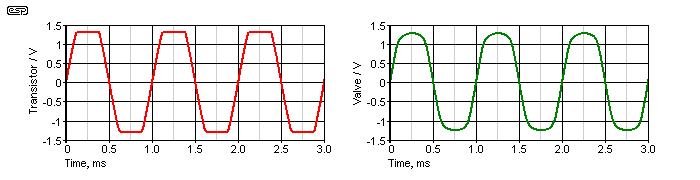
I wasn't familiar with implementation of soft clipping before, and I read quite a bit to find out the various methods available for this. I landed on probably the most common one though: soft clipping algo
4. Harmonics
Gotta love some harmonics in your kick. Turning this up from 0 increases the level of the additional harmonics. I implemented this parameter quick and dirty for now, but it sounds good, so maybe I leave it. The principle of adding harmonics is simply adding some more frequencies to the sound than just the base frequency. I gives the kick some body and tonal content. I decided to add 3 frequencies. The first is fixed at 220Hz, the 2nd and 3rd are multiples of the base frequency, in this case the 2nd is 7.8x the base frequency and the 3rd is 10.2x the base frequency. These are chosen without any theoretical backing, just cause it sounds good. Also the 2nd frequency is slightly more present than the 1st and 3rd. Also for fun I added some randomness to each harmonic frequency, which means that each hit with the same parameter value for harmonics, will have an every so slightly different sound.
Hihats
For the hihat, I chose the route of least resistance whihc is a straight up whitenoise hihat. I took some inspiration from the track Clipper by Autechre, which has this very dry minimal beat with a clear whitenoise hihat (and snare). These sounds seem to have a different pitch, however the thing with whitenoise is that it has no pitch, so we are actually talking filter here. By bandpassing part of the whitenoise spectrum we can trick the ears into hearing a pitched up and down whitenoise. But that brought up the existential question of how to program a filter. This is where the Audio programming book (see link above) came in handy, as it has a good section on filters. I chose a 2nd order Butterworth bandpass filter, partially cause I easily could find the precalculated coefficients (path of least resistance). It sounded nice straight off the bat, so I stuck with it. Could think about adding resonance, but that is for later.
Another cool thing in the Autechre song is that the envelope of the hat is not a classic exponential or linear decay, but more a constant volume and sudden stop. This gives the sound a glitchy feel, which is my jam. So I added the option to choose either a classic or full-stop decay for each hit individually.
Snare
So initially as a placeholder I combined a high pitched kick with some whitenoise transient for a snare drum. This actually sounded pretty nice, considering it basically was a combination of my 2 other sounds. But I want a more distinct 3rd sound, and think FM is the way to go. I haven't gotten round to programming it yet, but it's next on the list.
Envelopes
Each sound needs an amplitude (volume) envelope. Where synths often use ADSR envelopes, this is less relevant for percussion. Often actually only a decay envelop is needed, i.e. we start high and quickly decrease volume before mellowing out the volume decrease towards the tail of the sound. For the kick I have included an attack envelope, as it can give a slight pumping effect which can be be nice if I'd want to use the kick to also make bass sounds. In addition a tiny attck can help with eliminating a clicking sound which can occur (especially noticable for low pitched instruments). For the hat we only use a decay envelope.
Initially I calculated the envelope for each timestep. However I stumbled upon a thread on the signal processing stackexchange where using lookup tables was advised: stackexchange thread. I also saw this method on the Mutable instruments github, and then realized it was actually Emilie who had responded in this thread. So that's enough proof for me, lookup tables it is! I added a python script, that writes these tables for you. Then it's a simple copy and paste job to get them in the envelopes.cpp file.
This has been a recap of my work so far. It isn't as detailed as I'd like, seeing as I started this blog a little late. Going forward I hope to provide some more details. Hope it gives some idea of my way of approaching the project. As I said there is little planning involved, we just go forwards and see where it takes goes. Next up is programming the last sound algorithm, FM synthesized snare.
Github PR #5: Add FM Hit
FM Hit
So the next step was to add an FM hit to the code as my third and (for now) final sound. For background on FM synthesis suggest you just google it, but the maths behind it is luckily very simple:
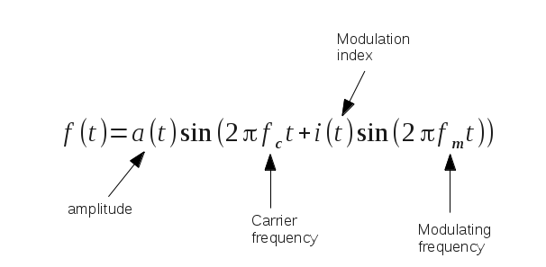
We have a carrier, and a modulator and for each timestep t we just calculate this formula. In this formula we can then paramterize the base frequency (f_c) and modulation amplitude (i(t)) and frequency (f_m). Bob's your uncle.
But the issue is that we need to set some limits. In theory we can have massive ranges for all these parameters which would yield a massive range of sounds, but this would make the sound hard to control. Also we could add multiple modulators or/and modulate the modulators and you quickly understand why FM synths are so hard to program. So what I decided to do is to open Ableton and take the Operator instrument, which is an FM synth, and start playing around. Just need to make sure we use only sinewaves for both the carrier and modulators, since I don't want to use anything more complicated in my program. Also we choose an fm-algorithm to suit my needs. I chose quite a simple algorithm, being 2 parallel modulators that modulate the carrier independently. This equates to just adding another (modulating frequency) term to the formula above. Then I just played around with the ratios and decays until I found a range that I think suits a snare type sound (it doesn't sound like your traditional snare though), but also can create some wacky sounds when pushed to the limit.
Since I have 2 modulators I have 2 ratios to set between modulating and base frequency. This seems overbearing, I'd rather have it simpler and control the ratios for both with only 1 input. So I chose the ratio of the 2nd modulator to be 3/7 of the 1st modulator. This provides a nice minor chord style harmonic whatever the setting of the input ratio. Also to keep things simple, the amplitude of the 2 modulators are linked and can't be set individually. Lastly the decay of all 3 waves are linked. This provides a good balance between flexibility on sound and complexity.
Initially I had the value for the amplitude of the modulating frequency range between 0 and unity. This is the classic way as far as I know. But then I found that pushing this amplitude over the unity (up to 100x) gave a nice overdriven sound. However this cool feature would cost a lot of precision in my fm_amount range. Suddenly the range is not from 0 to 1 but from 0 to 100 (imagine setting this with a potentionmeter). So I chose to have 2 settings instead; normal FM and bonkers FM, where bonkers sets the range from 0 to 100. Now you can easly switch for each hit and tell the program to deliver a normal or bonkers hit.
Lastly I found the sound was lacking some punch. The initial hit was just a tad weak. To spice this up I decided to add a splash of whitenoise. Basically a hihat sound, but with a very short decay (80ms). This is just to beef up the transient. I thought of just summing the original sound with this whitenoise transient, but thought that would be a bit messy. An easier way of adding this is just to simply add another modulator to the carrier, but instead of a periodic function as in the formula above, we just sample from a uniform distribution between -1 and 1. This worked nicely, only hassle was that the program needs to calculate 2 envelopes for the FM hit now; 1 for the main hit and 1 for the transient (since the lengths of these envelopes aren't the same). An alternative would be to just store the whitenoise sample as a vector. This would be very easy to create, and I made a python file that does just this. The issue is that it would take up a lot of memory, and I don't know if that is feasible as we have a limited amount in our chip. A memory vs speed issue, which we'll probably get back to later on.
Github PR #6: Refactor and optimize
Refactor and optimize
Thought I'd write a post per pull request instead of just referencing a commit hash, since that makes it clear and nice to backtrack later on if needed. This PR is not too interesting though, some refactoring mainly and small updates. What I did was:
1. Removed the old snare drum remnant from the project
2. Add velocity parameter to hihat and snare (I forgot to add this there, but simply took the one from the bassdrum)
3. Cleaned up and consolidated some code
4. Used the lookup table for the envelope also for the bassdrum. Made this into a common envelope function which is shared across instruments
5. Remove floating points (incomplete)
The last one is a headscratcher, I noticed from the Mutable Instruments Peaks github project that there was no use of floats whatsoever in the program (I did ctrl+f to check). I, on the otherhand, have floating points scattered throughout. Some googling quickly led to the insight that it can be beneficial to avoid floats, especially when programming on embedded systems (something to do with processor intrinsics that I don't understand). So fair enough, I saw in the mutable project they were using fixed points instead of floating points. I needed to watch some youtube to understand how this works, since I hadn't encountered fixed point arithmatic before. But the concept was pretty simple, so I thought it would be relatively straightforward to implement. It wasn't though, I got stuck on my periodic functions which are used to calculate my sine waves (which are used a lot). Couldn't quickly figure out how to scale these functions from the floating point world to the fixed point world.
That's what you get for just starting before thinking. But no matter and after doing a little work with fixed points on my bassdrum, I decided to park this issue for future Morten to solve. I'm sure it can be done, I could e.g. make use of lookup tables for my sinewaves. At the moment though it was harshing my vibe and I want to continue writing a draft for my sequencer so I can produce a beat that doesn't sound like 2 drunk people hitting pots and pans.
Github PR #7: Initialize rhythmic sequencer (PR partially covered in this entry)
Initialize rhythmic sequencer
This PR is quite a biggy, containing the foundation for my sequencer. It sort of evolved while I was working on it, starting out as being a sequencer completely dominated by randomness to a sort of rhythmic sequencer with dialled in randomness. I'm really happy with the result, although I'm sure it needs (significant) tweaking once I start prototyping it. But think the foundation is solid. Also I have now implemented 1 type of algorithm, I have ideas for more but these I will put on the backburner.
I started out coding the simplest sequencer I could think of; a sort of random hit sequencer. What this basically meant was that for each instrument we provide a probability that it is hit. Then for each 16th step we draw a sample and if this sample is lower than the provided probability we 'hit' the instrument. In addition we also randomly sample values for the sound parameters of the various drums. This sampling method is purely random and not musical whatsoever. However the results were actually really wicked and a good starting point.
Next step was making it more musical. For this I drew inspiration from my very limited experience of playing the drums, or more specifically from a youtube lesson on improvising on drums. Since this is what we essentially are planning to achieve I guess. The instructor (Jonathan Curtis) said he'd choose a rhythmic pattern and use this as the backbone for the improvisation. He used the clave as example, which is a classic and looks like this:
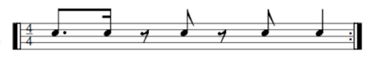
But there are many others, like a tresillo and a 4 to the floor. So I chose to use these patterns as a foundation of my drum machine improvisation algorithm. So I assigned the 1st potentiometer (virtual for now) to determine which rhythmic pattern to use. A pattern is saved in the program as a simple 1x16 array (16 steps), with 1s for each 'hit' in the rhythm and 0s otherwise. So unfortunately no triplets for now. Next up is how to determine what happens when my sequencer reaches a 'hit'.
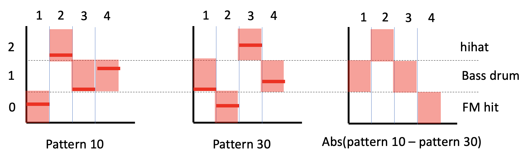
We have 3 drum sounds, and we have to determine which one is hit. I want this choice to be deterministic from the outset, and then randomization can be dialled in. I played with various ways of doing this in my head, but landed on a solution inspired by the bastle kastle drum machine. This drum machine has a pattern generator which is a simple 8 step pattern where each step outputs a value in a predefined range. I took this idea of using a pattern to decide my drum sound, but made it a bit more complicated (at least for myself). I created 50 random 16 step patterns, where each step in the pattern is a random value between 0 and 100. I used python to generate these and then just copied the output to my code. Then I added 2 potentiometers, which both scroll through these 50 patterns. So for illustration imagine that pot 1 is at 1/5 and pot 2 at 3/5 and we are at step 3 of our 16 step sequence. This means pot 1 selects pattern number 10 and pot 2 selects pattern number 30. Now hang in, for the drum sound to be chosen we take the value at step 3 for pattern 10 and map this to a value between 0 and 2. And the same for step 3 of pattern 30. We then take absolute difference between these values to end up with our final value, which is still in the range 0-2. Now for the last step, we need to map this value to an instrument. In my case a 0 corresponds to the FM hit, a 1 to the bassdrum and a 2 to a hihat. This mapping is not chosen at random. Since we subtract 2 random values and then take the absolute value we are not anymore dealing with a uniformly distributed variable but a triangular distributed variable. Therefore the chance of ending up with 0, 1, 2 is not equal. At first this seemed like a nuisance and broke my plan, but actually I can use this too my advantage. The result that is most probable in my case is 1. Since this is the drum that will be hit on the beat of the rhythmic pattern it makes sense to have a drum sound that emphasizes this rhythm. A bass drum is the instrument for this in my opinion. Next up in probability is 0, and follwoing the same logic this would be a snare. The least suited instrument to emphasize the rhythm is the hihat and therefore this gets the value with the least probability. Hereby a picture that hopefully clarifies the above a bit better (note that I have 4 steps in the pattern, this is for illustrative purpose. In actual fact there are 16 steps)
No future code blogs for the time being, as this was consuming a lot of time. Will return at a later stage when the code is finalised.